TC.GSS Series
Options and Functions for the TC.GSS Series
HMI Display
Front panel integrated control unit with graphic LC-Display, select wheel, push buttons and interactive text menus

19” Remote Control Unit (RCU.RM)
19-inch rack-mount remote control unit with graphic LC-Display, select wheel, push buttons and interactive text menus
19” Remote Control Unit incl. Emergency Stop Button (RCU.RM.2CH)
19-inch rack-mount remote control unit with emergency stop button (2-channel) and with graphic LC-Display, select wheel, push buttons and interactive text menus
Desktop Remote Control Unit incl. Stop Switch (RCU.DT.1CH)
Desktop remote control unit with stop switch (1-channel) and with graphic LC-Display, select wheel, push buttons and interactive text menus

CAN Interface (CANmp)
The rear panel integrated CAN multi-protocol (CANmp) interface has a 1 kHz data rate, a 12-bit resolution, and is adaptable to any proprietary CAN bus. In addition, it supports dbc file handling.
CANopen Interface
The rear panel integrated CANopen interface includes RS232REAR, standard RS-232 on front panel not usable
USB Interface
The rear panel integrated USB interface includes RS232REAR, standard RS-232 on front panel not usable
CANopen + USB Interface
The rear panel integrated CANopen and USB interface includes RS232REAR, standard RS-232 on front panel not usable
Ethernet Interface
The rear panel integrated Ethernet interface includes RS232REAR, standard RS-232 on front panel not usable
LXI Interface
The rear panel integrated LXI interface includes RS232REAR, standard RS-232 on front panel not usable
IEEE Interface
The rear panel integrated GPIB / IEEE488.2 / SCPI interface includes RS232REAR, standard RS-232 on front panel not usable
RS232REAR Interface
The rear panel integrated RS-232 interface includes RS232REAR, standard RS-232 on front panel not usable
RS422 Interface
The rear panel integrated RS-422 interface includes RS232REAR, standard RS-232 on front panel not usable
Battery Simulation Software (BatSim)
Batteries play a key role as energy storage elements in the fields of solar energy plants, electro mobility and all kind of grid independent technical equipment. Due to their product specific properties, batteries have to be tested for each specific application, taking into account all possible electrical and environmental situations. Up to now, such evaluations and tests were performed mostly with real batteries or battery stacks.
Over the past years, engineers began to substitute real bulky and expensive batteries by electronic power supplies in order to simulate at the least the discharge behaviour of the real battery. By this, one of the most important drawbacks of real batteries could be avoided: In the case of a circuit failure or a short circuit, real batteries are driving nearly unlimited current endangering personnel in the vicinity by fire or splatters of melted metal. Modern power supplies dispose of a fast acting current limit preventing too high a current from flowing.
Advanced battery simulation however means not only to reproduce the discharge curve more or less accurate, but rather to cover the full characteristics of electro-chemical storage element during any charge or discharge activity. Due to the bidirectional current flow of each rechargeable battery, simulation also has to cover the full range of charging and discharging currents.
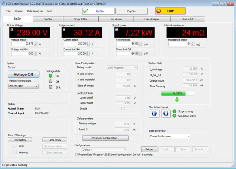
REGATRON battery simulators are made up of a bidirectional and programmable REGATRON DC power supply equipped with the powerful application software BatSim. This software is resident onboard the DC power supply respective onboard the master unit of a bigger system and is handled by a PC shell software. The BatSim computing process is running in real-time perfectly matched to the internal timing of the DC power supply. By this, an optimum computing rate can be reached leading to nearly one-to-one time behaviour even in the case of steep changes in charge/discharge current.
Each battery type reacts in a typical manner to charge and discharge currents in terms of ‘state of charge’, cell voltage, ohmic and parametrical losses, polarisation voltages and so on. REGATRON BatSim software/firmware is based on specific mathematical models considering these interdependences in an optimum method. Nevertheless, the operator may fine-tune the model by a number of well-defined parameters in order to match the models answer to an existing real value table.
Select from the following base models:
- Li-Ion
- Lead-Acid
- NiMH
- NiCd
Define and enter all important process parameters related to your application as:
- Cell capacity
- Number of cells in series, parallel or mixed
- Simulation cut-off values
- State of charge
Use the following features:
- Multi-channel data-logger with EventMarkers as time stamps, file export in .csv file type
- Record-to-file capabilities freely configurable by scripting language
- Multi-trace data analysis (e.g. comparison) of different measurements over the same time axis by a DataAnalyser
Battery Testing and Cycling Software (BatControl)
With a look to the growing market of e-mobility and the increasing demand for PV energy storage, testing and cycling of real battery systems is of great importance. Real tests are the key to authentic ratings for a given system under given circumstances.
Testing and cycling of batteries with the aid of REGATRON bidirectional DC power supplies is of double benefit:
a) The discharge energy is not lost, but reinjected to the grid with optimum performance
b) REGATRON BatControl application software supports the test engineer by a number of praxis-proven tools
By this, a given test procedure is set by a few klicks and may last hours or even days.
BatControl software offers:
- Possibility to define charge (and discharge) algorithms
- Possibility to run driving cycles (own or according to already defined standards)
- Possibility to replay previously recorded discharge/charge data
- Possibility to undergo the battery with the real electric load created by a driving test – just inside your lab…
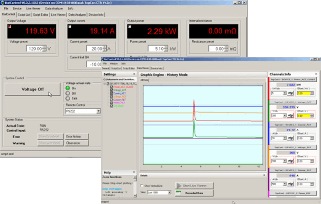
BatControl allows selecting and running so-called „BatScripts“. These scripts automate the otherwise manually given commands to the TC.GSS power supply. Scripts allow running the commands according to a timeline; hence easily let the user define aspects like „charge that battery with 8 Amps for 90 minutes”.
BatControl at a glance:
- Implementation of charge and/or discharge routines, access to internal charge counter
- Burdens the battery according to given drive cycles
- Discharges/charges the battery according to recorded data (record & replay)
- Automatic execution of sequences of TC.GSS power supply commands
- Possibility to run driving cycles (own or according to already defined standards)
- Possibility to replay previously recorded discharge/charge data
Time function engine (TFEAAP)
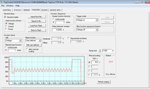
The time-based function engine TFE is a powerful function creator working in the time domain able to generate nearly each voltage/current/power-to-time function. TFE runs as a firmware in real-time onboard of each REGATRON DC power supply. Programming and setup of TFE functionality is done by TopControl Software – the versatile application and service tool coming with each DC power supply. This powerful tool allows for entering, saving and recalling of complex test sequences. Base functions like sine, triangle, rectangle can be directly called. Furthermore user defined curves with up to 1000 points and linear interpolation can be entered and stored. Amplitude, frequency, offset and symmetry can be combined in a simple way. User-defined function sequences with a resoluation of 50 µs can be saved in the memory of TC.GSS and may be recalled at any time. Exporting, importing and even off-line data processing is possible with a text editor.
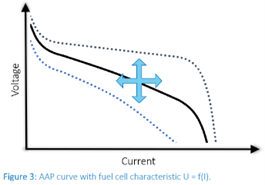
A second feature of time-based TFE is called application area programming AAP. This feature allows the definition of a functional interdependency of DC output quantities like current, voltage or power compared to another process variable. Function is given by a user-defined slope or a table of value pairs. By this, TC.GSS power supply behaves like a two pole network with defined characteristics. As mentioned under TFE heading, AAP is refreshed also every 50 µs, ensuring a fast response to any parameter variation. Relevant example: voltage dependent output current of a PV-panel or current dependent output voltage of a fuel cell.
Safety Interface (ISR)
Integrated safety relay (ISR) for increased emergency stop reliability, supporting performance level PL c / PL e according to EN ISO 13849
Reverse Polarity Protection and Pre-charge Circuit for Battery Testing (RPP)
Working with high power batteries creates several risks which must be thoroughly considered for a safe operation. Besides the well-known fact that voltages, currents and temperatures must be monitored and kept in a safe range, the connection of a battery to a load or battery tester also requires appropriate attention with regard to polarity and voltage levels. To increase personnel and equipment safety, REGATRON offers an intelligent option for the two major risk factors when physically connecting a battery to the battery tester. This very helpful option addresses the following two safety hazards:
- Sparks, fire, welding and damage to the battery and the battery tester as a result of connecting the battery with wrong polarity
- Sparks, possible welding and high inrush currents as a result of connecting electrical storage elements to the battery tester with unmatched voltage levels
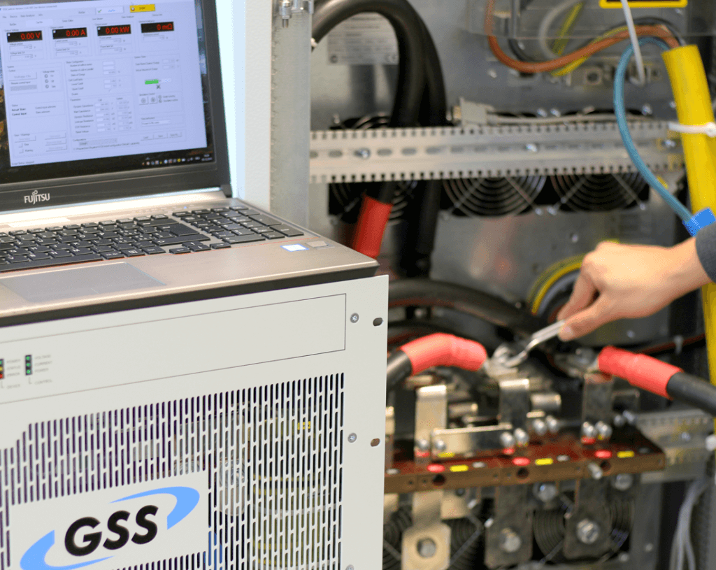
In voltage off state, the output stage of the REGATRON battery tester is isolated from the output clamps by means of an open power contactor. Connecting the battery to the tester even with reversed polarity is therefore without any risk in this state. Attempting to give a voltage on command with wrong polarity will block any further action and the battery tester will indicate „wrong polarity“. If the applied voltage is of correct polarity but higher than the voltage set value (e.g. a charged battery is being connected), the battery tester’s output voltage will be automatically matched to the battery voltage in order to avoid high inrush currents at voltage on.
Safety Extra Low Voltage 60 V (SELV)
SELV 60 V according to EN 60950-1
AC Filter Discharge (XCD)
Discharging of the AC filter (XCD), is mandatory when using the device with a plug connection. XCD ensures a discharge time of the AC filter <1 s as required by EN 62477-1
Protection Covers
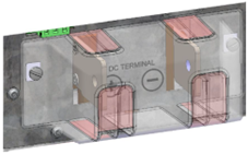
– DC terminal protection cover with transparent polycarbonate and quick-acting closure
Order Code: PAC.G.DC
– AC terminal protection cover with transpartent polycarbonate and quick-acting closure
Order code: PAG.P9.AC
AirFilter
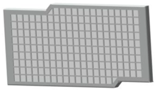
– Front-panel-mounted air filter
– Metal frame, replaceable filter mat
– Recommended for use in dusty environments and with IP20 cabinets
Order code: AIRFILTER.9
Liquid Cooling (LC)
Liquid cooling is carried out at power supply module level. A inlet temperature of 18 to 35°C is recommended. The advantage of liquid cooling of power supply units is that the dissipated heat can be removed from the laboratory / test bench without the need for costly A/C installations.
Ruggedization against Shock and Vibration (RUGG.SAV.G)
For operation in mobile applications under enhanced requirements to vibrations, shock and ever-changing environments. TC.GSS provides different environmental protection levels. To be ordered separately or in combination with RUGG.ENV.G.
Protection against Humidity and Pollution (RUGG.ENV.G)
All printed circuit boards (PCB) are covered with a conformal coating to provide additional protection against environmental influences such as humidity and pollution. TC.GSS provides different environmental protection levels. To be ordered separately or in combination with RUGG.SAV.G.
Rack Integrated System Solutions
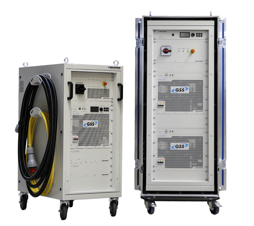
– Mobile rack solutions on castors up to 128 kW
– Air- or liquid cooled solutions
– Flight case cabinet design for frequent relocation to different test sites
– Third-party product integration like AC&DC cables and safety components to reach performance level e (PL e) according ISO EN 13849-1
– Optional insulation monitoring unit
– Easy reconfiguration between parallel, series, and mixed operation by means of DC switch panel

Benötigen Sie die richtige Energie-Lösung?
Wir helfen Ihnen dabei, die ideale Konfiguration zu finden. Kontaktieren Sie uns noch heute für kompetente, individuelle Unterstützung.
